MPI Ultrasonics - sonic and ultrasonic processing technology
Enter the World of Ultrasonics Macro Engineering
Ultrasonic Cleaning in Liquid CO2
Multifrequency Ultrasonic Actuators with Special Application to Ultrasonic Cleaning in Liquid and Supercritical CO2
Carlo Devittori†, Philipp Widmer†, Flavio Nessi†, Miodrag Prokic‡
‡ MPI (MP Interconsulting); - R&D activities in Ultrasonics
Marais 36, 2400 Le Locle, Switzerland
+41-32-9314045,
web: mpi.powerultrasonics.com,
e-mail: mpi@powerultrasonics.com
† ECO2 SA, Supercritical Fluid Technology for cleaning, processing and fine chemicals,
6805 Mezzovico, Switzerland
+41-91-6122100,
web: www.eco2.ch,
e-mail: info@eco2.ch
Keywords: Multifrequency Ultrasonic Transducers, Supercritical Fluid Technology, Supercritical Fluid Cleaning, Ultrasonic liquid-CO2 Cleaning
Abstract
The collaboration between ECO2 SA and MPI resulted in the realization of an industrial plant for the precision cleaning of mechanic, micro mechanic, electronic and microelectronic industry parts, based on the solvent-power of supercritical CO2 and on the cleaning power of ultrasonic energy propagated in liquid CO2. The plant, already productive, performs the cleaning of 15 kg/h of precision writing balls, and it has been successfully tested for other industrial applications. Substitution of CFC, chlorinated solvents and detergents, absence of contaminated solutions and vapor emissions and improvement of the surface cleanness, are the most important results. The propagation of ultrasonic energy in the homogenous and pressurized medium like liquid CO2 (T< 32°C; P> 60 bars) is realized using a novel ultrasonic structural, multifrequency actuator, able to initiate ringing and relaxing, multimode mechanical oscillations (harmonics and sub harmonics) in an autoclave with very thick walls, producing pulse-repetitive, phase, frequency and amplitude-modulated bulk-wave-excitation. Such ultrasonic driving is creating uniform and homogenous distribution of acoustical activity on a surface and inside of the vibrating system, while avoiding creation of stationary and standing waves structure, making that the complete vibrating system (autoclave) is fully agitated.
Introduction
The liquid, supercritical CO2 precision cleaning project proposed by Swiss company ECO2 SA was recognized and encouraged by the Swiss Federal Bureau for environmental protection (BUWAL) because of its potential to substitute chlorinated and fluorinated solvents (CFCs) with inert and non toxic carbon dioxide. The project was developed around a specific industrial application - cleaning of precision steel and tungsten carbide balls, for ballpoint pens (these balls, with diameters from 0.5 to 1 mm, are contaminated during production by lubricant oils, metal powders and very fine abrasive powders, and must be cleaned to a very high degree, verified by SEM, using 5000 to 10000 magnification). An industrial ultrasonic-CO2 pilot unit has been built for this purpose, and is also applicable to other products. The plant is currently operating well and has the capacity to clean small solid balls at the rate of 15 kg/h.
ECO2 SA is a Swiss company, active in Supercritical Fluid Technology for cleaning, liquid processing and exploitation of fine chemicals. MPI, also a Swiss company, develops challenging projects in Ultrasonics.
In this new cleaning process, the oils are removed from the surface by the detergent action and solvent-power of the supercritical liquid CO2, while the solid residues are dislodged by sonic and ultrasonic wave agitation. Conventional ultrasonic baths, using water or other conventional solvents, operate at or close to atmospheric pressure. In the case described here, the liquid (CO2) is homogeneous, pressurized to at least 60 bars and must be kept at a temperature of no more than 31°C. Under these conditions conventional high power ultrasonic systems are ineffective. In this project a novel multifrequency and multimode (sweeping frequency) ultrasonic source was developed for optimal propagation of ultrasound into the internal cleaning reactor space (Patent EP 1 060 798 A1; -see more about Multifrequency Ultrasonic Structural Actuators in the second part of this paper).
2. Cleaning System
A basket containing the small solid balls is placed in a pressurized autoclave that has very thick stainless steel walls (approx. 20 to 25 mm). Inside this pressurized autoclave (or ultrasonic cleaning reactor) the basket is rotated by an external motor at a programmable rate between 10 and 150 rpm. The ultrasonic energy is applied for a period of 4-10 minutes during the washing phase with liquid CO2. Cleaning residuals and remaining powders are transported out of the autoclave by a continuous current of liquid CO2, generated by a diaphragm pump with a flow rate of 30-100 Kg/h. At the end of the cleaning cycle the liquid and/or supercritical CO2 is depressurized and vaporized. This dramatically reduces its solvent power for complex and heavy oils so that all cleaning residuals, such as oil-remains and powders, are deposited in the separator-unit. To complete the cycle, the vaporized CO2 is filtered, condensed and reintroduced to the autoclave.
A complete washing cycle takes 40 min. The volume of the autoclave in question is 10 liters, which allows a batch of approx. 15 kg of small tungsten carbide or metal balls.
3. Experimental Results
Production and experimental batch testing has shown that this technology allows an improvement of the industrial cleaning quality standard (degree of cleanness of balls’ surfaces), an increase in productivity, an increase in operators safety (elimination of solvent vapor emission), and it becomes environment friendly (there isn’t soil contamination trough solvent-vapor diffusion), including other benefits such as: no-need for detergents ands solvents, water cannot be contaminated, there isn’t waist of cleaning oils.
Figure 1 shows the CO2 cleaning-process block-diagram, Figure 2 presents the block diagram of a multifrequency structural actuator, while figures 3 and 4 are photos of the industrial pilot unit developed. Figures are shown at the end of this paper.
The plant has been successfully tested for precision balls used in ball-pens, for surgical instruments, for medical implants (screws and prostheses), jewelry, for electronic and microelectronic parts and products, for car and aeronautics industry etc. The cleaning degree and quality of the surface processing was checked by means of electronic microscopy (see Figures 5, 6 and 7).
4. MULTIFREQUENCY ULTRASONIC STRUCTURAL ACTUATORS
The high power ultrasonic system used in this process generates multimode mechanical oscillations in the cleaning reactor, or autoclave over a wide frequency range. This is in contrast to conventional power ultrasonic systems, which operate at a single frequency. In addition the method of driving these transducers is optimized.
Every elastic mechanical system has many vibration modes, plus harmonics and sub harmonics, both in low and ultrasonic frequency domains. Many of vibrating modes could be acoustically and/or mechanically coupled, and others would stay relatively independent. In our multimode transducer we have the potential to synchronously excite many vibrating modes (including harmonics and sub harmonics), producing a uniform and homogenous repetition of high intensity vibrations.
In our system we insure that the oscillations are not random - rather they follow a consistent pulse-repetitive pattern, frequency and amplitude-modulated by the control system. This avoids the creation of stationary or standing waves (typically produced by traditional ultrasonic systems operating at a single frequency) that generate regions of high and low activity.
This technique (multimode excitation) is beneficial in many other applications, e.g. Liquid processing, fluid atomization, powders production, artificial aging of solids and liquids, accelerated stress relief, advanced ultrasonic cleaning, liquid metal treatment, surface coating, accelerated electrolysis, mixing and homogenizing of any fluid, waste water treatment, water sterilization, accelerated heat exchange...
A multifrequency ultrasonic structural actuator (see Fig. 2) consist of:
- Sweeping-frequency Ultrasonic Power Supply (including all regulations, controls and protections),
- High Power Ultrasonic Converter (see Patent EP 1 060 798 A1),
- Acoustical Wave-guide (metal bar, aluminum, titanium), which connects ultrasonic transducer with an acoustic load, oscillating body, resonator...
- Acoustical Load (mechanical resonating body, sonoreactor, radiating ultrasonic tool, sonotrode, test specimen, vibrating tube, vibrating sphere, a mold, solid or fluid media, autoclave…),
- Sensors of acoustical activity fixed on/in/at an Acoustical Load (accelerometers, ultrasonic flux meters, cavitation detectors, laser vibrometer/s…), which are creating regulation-feedback between the Acoustical Load and Ultrasonic Power Supply.
A strong mechanical coupling of high power ultrasonic converter (B) to the test specimen or acoustical load (D) is realized using acoustic-wave guide metal bar (C). Ultrasonic converter (B) is electrically connected to the ultrasonic power supply (A), or ultrasonic multimode generator. Acoustic activity sensors (E) are realizing feedback (for the purpose of automatic process control) between Acoustical Load (D) and Ultrasonic Power Supply (A).
Operating Principles
Ultrasonic Converter (B), driven by Power Supply (A), is producing a sufficiently strong pulse-repetitive multifrequency train of mechanical oscillations or pulses. Acoustical load (D), driven by incoming frequency and amplitude modulated pulse-train starts producing its own vibration and transient response, oscillating in one or more of its vibration modes or harmonics. As the excitation changes, following the programmed pattern of the pulse train, the amplitude in these modes will undergo exponential decay while other modes are excited.
A simplified analogy is a single pulsed excitation of a metal bell that will continue oscillating (ringing) on several resonant frequencies for a long time after the pulse is over. How long each resonant mode will continue to oscillate after a pulse depends on mechanical quality factor in that mode.
Every mechanical system (in this case the components B, C and D) has many resonant modes (axial, radial, bending, torsional, …) and all of them have higher frequency harmonics. Some of resonant modes are well separated and mutually isolated, some of them are separated on a frequency scale but acoustically coupled, and some will overlap each other over a frequency range - these will tend to couple particularly well.
Since the acoustical load (D) is connected to an ultrasonic converter (B) by an acoustical wave-guide (C), acoustical relaxing and ringing oscillations are traveling back and forth between the load (D) and ultrasonic converter (B), interfering mutually along a path of propagation. The best operating frequency of ultrasonic converter (B) is found by adjustment when maximum traveling-wave amplitude is reached, and when a relatively stable oscillating regime is found. The acoustical load (D) and ultrasonic converter (B) are creating a "Ping-Pong Acoustical-Echo System", like two acoustical mirrors generating and reflecting waves between them. For easier conceptual visualization of this process we can also imagine multiple reflection of a laser beam between two optical mirrors. We should not forget that the ultrasonic converter (B) is initially creating a relatively low pulse frequency mechanical excitation, and that the back-and-forth traveling waves can have a much higher frequency.
In order to achieve optimal and automatic process control, it is necessary to install an amplitude sensor (E) of any convenient type (e.g. accelerometer, ultrasonic flux sensor) on the Acoustical Load (D). The sensor is connected by a feedback line to the control system of Ultrasonic Power Supply (A).
There is another important effect related to the ringing resonant system described above. Both the ultrasonic source (B) and its load (D) are presenting active (vibrating) acoustic elements, when the complete system starts resonating. The back-forth traveling-waves are being perpetually reflected between two oscillating acoustical mirrors, (B) and (D). An immanent (self-generated) multifrequency Doppler effect (additional frequency shift, or frequency and phase modulation of traveling waves) is created, since acoustical mirrors, (B) and (D), cannot be considered as stable infinite-mass solid-plates. This self-generated and multifrequency Doppler effect is able to initiate different acoustic effects in the load (D), for instance to excite several vibrating modes in the same time or successively, producing uniform amplitude distribution of acoustic waves in acoustic load (D), etc. For the same reasons, we also have permanent phase modulation of ultrasonic traveling waves (since opposite-ends acoustic mirrors are also vibrating). We should strongly underline that the oscillating system described here is very different from the typical and traditional half-wave, ultrasonic resonating system, where the total axial length of the ultrasonic system consists of integer number of half-wavelengths. Generally speaking, here we do not care too much about the ultrasonic system geometry and its axial (or any other) dimensions. Electronic multimode excitation continuously (and automatically) searches for the most convenient signal shapes in order to excite many vibration modes at the same time, and to make any mechanical system vibrate and resonate uniformly.
In addition to the effects described above, the ultrasonic power supply (A) is also able to produce variable frequency-sweeping oscillations around its central operating frequency (with a high sweep rate), and has an amplitude-modulated output signal (where the frequency of amplitude modulation follows sub harmonic low frequency vibrating modes). This way, the ultrasonic power supply (A) is also contributing to the multi-mode ringing response (and self-generated multifrequency Doppler effect) of an acoustical load (D). The ultrasonic system described here can drive an acoustic load (D) of almost any irregular shape and size. In operation, when the system oscillates we cannot find stable nodal zones, because they are permanently moving as a result of the specific signal modulations coming from Ultrasonic Power Supply (A)).
It is important to know that by exciting an acoustical load (D) we could produce relatively stable and stationary oscillations and resonant effects at certain frequency intervals, but also dangerous and self-destructive system response could be generated at other frequencies. Everything depends on the choice of the central operating frequency, sweeping-frequency interval and ultrasonic signal amplitudes from the ultrasonic power supply (A). Because of the complex mechanical nature of different acoustic loads (D), we must test carefully and find the best operating regimes of the ultrasonic system (B, C, D), starting with very low driving signals (i.e. with very low ultrasonic power). Therefore an initial test phase is required to select the best operating conditions, using a resistive attenuating dummy load in serial connection with the ultrasonic converter (A). This minimizes the acoustic power produced by ultrasonic converter, and can also dissipate accidental resonant power. When the best driving regime is found, we disconnect thedummy load and introduce full electrical power into ultrasonic converter. The best operating ultrasonic regimes are those that produce very strong mechanical oscillations (or high and stable vibrating, mechanical amplitudes) with moderate output (electric) power from the ultrasonic power supply. The second criterion is that thermal power dissipation on the total mechanical system continuously operating in air (with no additional system loading) is minimal. Differently formulated, low thermal dissipation on mechanical system (B, C, D) means that the ultrasonic power supply (A) is driving the ultrasonic converter (B) with limited current and sufficiently high voltage, delivering only the active or real power to a load. The multifrequency ultrasonic concept described here is a kind of "Maximum Active Power Tracking System", which combines several PLL and PWM loops. The actual size and geometry of acoustical load are not directly and linearly proportional to delivered ultrasonic driving-power. It can happen that with very low input-ultrasonic-power, a bulky mechanical system (B, C, D) can be very strongly driven (in air, so there is no additional load), if the proper oscillating regime is found.
Other Applications of Multifrequency Actuators
The spectrum of various imaginable applications related to above described multifrequency structural ultrasonic actuators could be illustrated by the following list:
1. Ultrasonic liquid processing
-mixing and homogenization
-atomization, fine spray production
-surface spray coating
-metal powders production and surface coating with powders
2. Sonochemical reactors
3. Water sterilization
4. Heavy duty ultrasonic cleaning
5. Pulped paper activation (paper production technology)
6. Liquid degassing, or liquid gasifying (depending of how sonotrode is introduced in liquid)
7. De-polymerization (recycling in a very high intensity ultrasound)
8. Accelerated polymerization or solidification (adhesives, plastics…)
9. High intensity atomizers (cold spay and vapor sources). Metal atomizers.
10. Profound surface hardening, impregnation and coating
-surface hardening (implementation of hard particles)
-capillary surface sealing
-impregnation of aluminum oxide after aluminum anodizing
-surface transformation, activation, protection
11. Material aging and stress release on cold
-Shock testing. 3-D random excitation
12. Complex vibration testing (NDT, Structural defects detection, Acoustic noise…)
-accelerated 3-dimensional vibration test in liquids
-leakage and sealing test
-structural stability testing of Solids
-unscrewing bolts testing
13.Post-thermal treatment of hardened steels (cold ultrasonic treatment)
-elimination of oxides and ceramic composites from a surface
-profound surface cleaning
-residual stress release, artificial aging, mechanical stabilization
14. Ultrasonic replacement for thermal treatment.
Accelerated thermal treatment of metal and ceramic parts in extremely high intensity ultrasonic field in liquids.
15. Surface etching
-abrasive and liquid treatment
-active liquids (slightly aggressive)
-combination of active liquids and abrasives
16. Surface transformation and polishing
-combination of abrasives and active liquid solutions
-electro-polishing and ultrasonic treatment
17. Extrusion (of plastics and metals) assisted by ultrasonic vibrations
-special ultrasonic transducers in a direct contact with extruder
18. Founding and casting (of metals and plastics) assisted by ultrasound
-vacuum casting, homogenization, degassing
-micro-crystallization, alloying, mixing of different liquid masses
19. Adhesive testing
-aging test
-accelerated mechanical resistance testing
-accelerated moisture and humidity testing
20. Corrosion testing
-in different liquids
-in corrosive liquid, vapor phase

Fig. 1 Liquid-CO2 Ultrasonic Cleaning, Process Diagram

Fig. 2 Block Diagram of a Multifrequency Structural Actuator

Fig. 3 Liquid-CO2 Ultrasonic Cleaning Industrial Pilot Unit

Fig. 4 Liquid-CO2 Ultrasonic Cleaning Autoclave
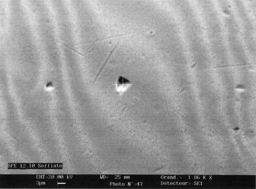
Fig. 5 SEM image of the cleaned surface of a precision writing ball at 1860 magnification

Fig. 6 SEM image of the cleaned surface of a precision writing ball at 10000 magnification

Fig. 7 SEM image of a traditionally cleaned surface of a precision writing ball (organic solvent/water/detergent-method)
Bibliography
- McHardy, J.; Sawan, P.; Supercritical Fluid Cleaning: Fundamentals, Technology and Applications, Noyes Publ., 1998.
- Dams, A..; Stoffübertragung bei der überkritischen Extraktion zweier schwerflüchtigen Aromaten und ihrer binären Gemische aus porösen Feststoffen, VDI Verlag, 1990, 2-10
- Smith et al., Proceedings of the 5th Meeting on Supercritical Fluids, ISASF, Nizza, 1998
- McHugh, M.; Krukonis, V.; Supercritical Fluid Extraction, Principles and Practice, Butterworth, 1984, 2-70
- Chen, J.; Yang, K.; Chen, S.; Tadafumi, A.; Kunio, A.; Proceedings of the 4th Int. Symp. on Supercritical Fluids, Sendai (Japan), 1977, 707-710
- Recanses, F.; Stüber,F.; Larrayoz; M.A.; Puiggené, J.; Proceedings of the 4th Int. Symp. SCF, Sendai (Japan), 1997, 395-397
- Dahmen et al., Precision cleaning using compressed carbon dioxide, Proceedings of the 7th Meeting on Supercritical Fluids, 12.2000, Antibes (F), page 369
- Lumia et al. Supercritical CO2 Cleaning: development of solvent-free cleaning process, Proceedings of the 7th Meeting on Supercritical Fluids, 12.2000, Antibes (F), page 375
- European Patent Application: EP 1 060 798 A1, Applicant & Inventor Miodrag Prokic, 2400 Le Locle, Switzerland.
©2001-2020 MPI Ultrasonics. All rights reserved.
